fmabattery
FMA 14.4V 4–5Ah Li-ion Rechargeable Battery for MOTOJET JM4S1P | 21700 4S1P
FMA 14.4V 4–5Ah Li-ion Rechargeable Battery for MOTOJET JM4S1P | 21700 4S1P
Couldn't load pickup availability
FMA 14.4V Li-ion Rechargeable Battery Pack for MOTOJET JM4S1P
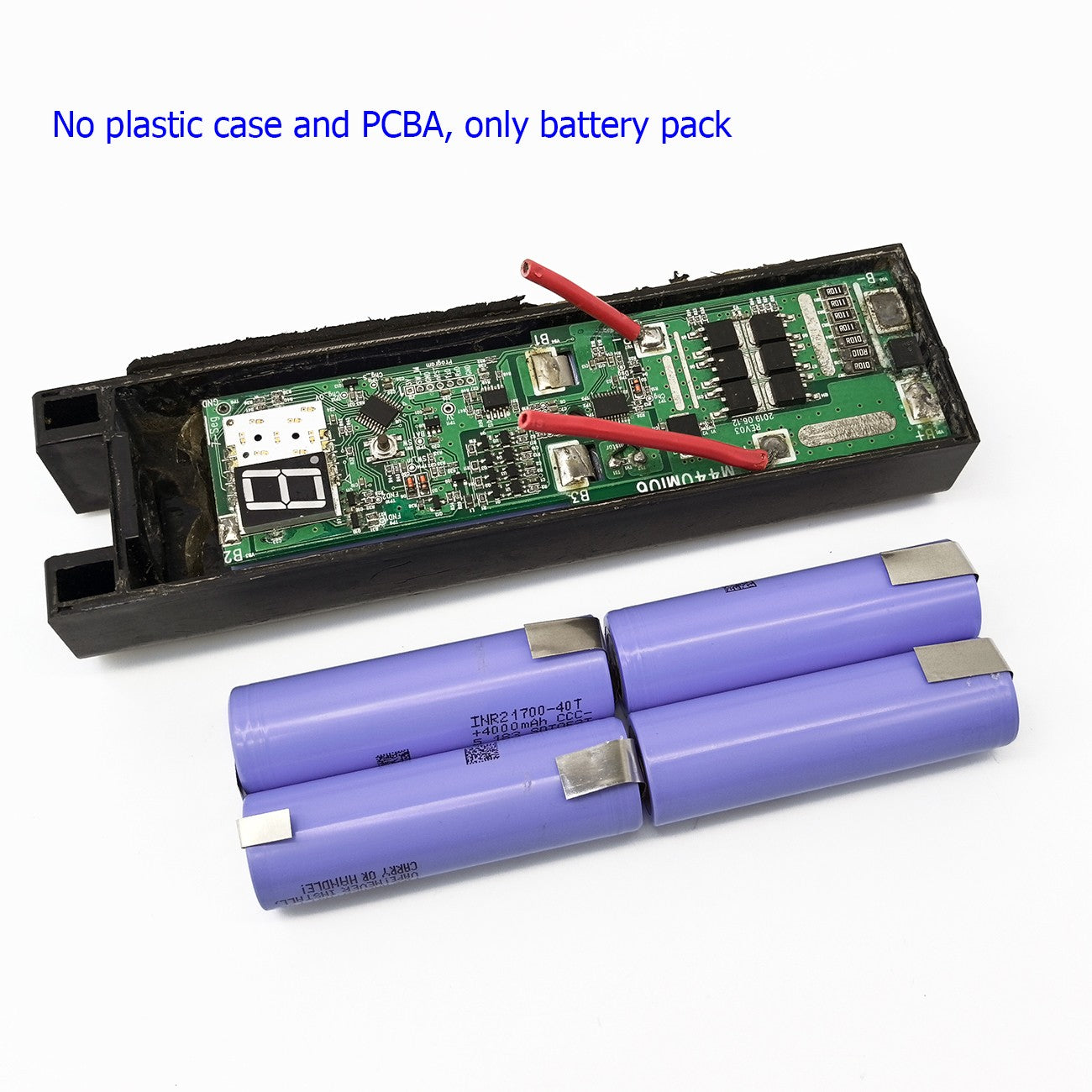
High-performance 14.4V lithium-ion battery pack built with premium 21700 cells in a 4S1P configuration. Designed as a direct replacement or DIY upgrade for MOTOJET JM4S1P applications. Available in three cell options: FMA 50E (5000mAh), Samsung 40T (4000mAh), and Samsung 50G (5000mAh). Each pack includes built-in PCM protection for safe and reliable operation.
⚠️ This is a DIY replacement cell pack. Installation requires soldering skills and basic electrical knowledge. Please read the full installation guide below before ordering.
Key Features
- Three Cell Options: FMA 50E 5000mAh / Samsung 40T 4000mAh / Samsung 50G 5000mAh
- Built-in PCM Protection: Overcharge, over-discharge, and short-circuit protection
- Premium 21700 Cells: High energy density for extended runtime
- 4S1P Configuration: 4 cells in series for stable 14.4V output
- Ni-plated Connection Tabs: Pre-welded nickel strips — ready to solder onto original PCB
- PVC Heat-Shrink Wrap: Durable cell packaging for protection and insulation
- Brand New: Cells from Samsung or FMA, assembled by FMA
Technical Specifications
| Nominal Voltage | 14.4V (4 × 3.6V) |
| Full Charge Voltage | 16.8V (4 × 4.2V) |
| Discharge Cut-off Voltage | 12.0V (4 × 3.0V) |
| Chemistry | Lithium-ion (Li-ion) |
| Configuration | 4S1P (4 cells in series) |
| Cell Type | 21700 |
| Cell Dimensions | 21mm (diameter) × 70mm (height) |
| Pack Dimensions | 21 × 42 × 143mm |
| Weight | ∼290g |
| Protection | PCM (overcharge / over-discharge / short-circuit) |
| Connection | Ni-plated tabs (no connector) — solder to original PCB |
| Cell Package | PVC Heat-Shrink |
| Compatible Application | MOTOJET JM4S1P |
| Condition | Brand New |
Cell Option Comparison
| Option | Cell Model | Capacity | Best For |
|---|---|---|---|
| FMA 50E | FMA 21700-50E | 5000mAh | Cost-effective, high capacity |
| Samsung 40T | Samsung INR21700-40T | 4000mAh | High discharge rate, power tools |
| Samsung 50G | Samsung INR21700-50G | 5000mAh | Maximum capacity, extended runtime |
Package Contents
- 1× FMA 14.4V Li-ion Battery Cell Pack (cell option as selected, with PCM, Ni-plated tabs)
DIY Skill Requirements
This product is an internal replacement cell pack intended for DIY battery rebuilding. It is not a plug-and-play replacement. Please confirm you have the following skills and tools before ordering:
| Requirement | Details |
|---|---|
| Soldering | Ability to solder Ni-plated tabs to PCB pads cleanly. A temperature-controlled soldering iron (350–400°C) is recommended. |
| Electrical Knowledge | Understanding of battery polarity (B+/B−), PCM wiring (P+/P−), and series cell configuration. |
| Multimeter Use | Ability to measure DC voltage to verify pack voltage and individual cell balance. |
| Mechanical Disassembly | Ability to safely open and reassemble the MOTOJET battery housing without damaging the casing or PCB. |
| Tools Required | Soldering iron, solder wire, multimeter, screwdriver set, plastic pry tools, adhesive (e.g. epoxy or hot glue) for resealing. |
| Safety Awareness | Knowledge of Li-ion battery safety: avoid short circuits, work in ventilated area, keep away from flammable materials. |
If you are not confident with any of the above, we recommend consulting a professional battery repair technician.
DIY Installation Steps
The following steps describe how to replace the internal cell pack in your MOTOJET JM4S1P battery housing:

| Step 1 — Open the Battery Housing | |
| Remove all screws from the MOTOJET battery casing. Use a plastic pry tool to carefully separate the top and bottom shells. Avoid forcing the casing — check for hidden clips or adhesive seams. |
[┌────────────┐]  ← Top shell
[│  MOTOJET  │]
[└────────────┘]  ← Bottom shell
        ↓ pry open
|
| Step 2 — Remove the Old Cell Pack | |
| Take a photo of the original wiring and tab connections before desoldering. Desolder the Ni tabs from the PCB pads (B+, B− and any balance leads if present). Remove the old cell pack from the housing. |
[PCB] ── B+ ◄── [Old cells]
      ── B− ◄──
        ↓ desolder tabs
|
| Step 3 — Solder New Cell Pack to PCB | |
| Place the new FMA cell pack into the housing. Solder the Ni-plated tabs to the corresponding PCB pads (B+ to positive pad, B− to negative pad). Ensure joints are clean and secure. Do not overheat — keep iron contact under 3 seconds per joint. |
[PCB] ── B+ ►── [New FMA pack]
      ── B− ►──
   ↑ solder iron ≤ 3s
|
| Step 4 — Test Voltage with Multimeter | |
| Before closing the housing, measure the output voltage at the battery terminals (P+ and P− on the PCB output side). Expected reading: 12.0V–16.8V depending on charge state. ✅ Voltage detected (12–16.8V): Proceed to Step 6. ❌ No voltage / 0V reading: The PCM may be in sleep mode — proceed to Step 5 to activate. |
[Multimeter] (+) ──► P+ (−) ──► P− Expected: 12.0–16.8V |
| Step 5 — Activate with Charger (if no voltage detected) | |
| If the multimeter reads 0V, the PCM protection circuit may have tripped due to deep discharge during storage. Connect a 4S Li-ion charger to the battery output terminals (P+/P−) for 30–60 seconds to wake up the PCM. Re-test voltage with the multimeter. The pack should now show a reading. If still no voltage after activation attempt, contact us. |
[4S Charger] (+) ──► P+ (−) ──► P− ↓ 30–60 sec [Re-test with multimeter] |
| Step 6 — Reassemble and Seal the Housing | |
| Once voltage is confirmed, carefully tuck all wiring inside the housing. Align the top and bottom shells and press together. Reinstall screws if applicable. Apply adhesive (epoxy or hot glue) along the seam to reseal the casing. Allow adhesive to cure before use. |
[┌────────────┐] [│ New cells │] [└────────────┘] ↓ seal with adhesive |
Important Cautions
- ⚠️ Li-ion only charger required. Use a 4S Li-ion charger (16.8V CC/CV). Never use Ni-MH, Ni-Cd, or unregulated chargers.
- ⚠️ Verify polarity (B+/B−) before soldering. Reverse polarity will damage the PCM permanently.
- ⚠️ Do not short-circuit the Ni tabs during installation. Insulate exposed tabs immediately after soldering.
- ⚠️ Do not charge a damaged, swollen, or leaking battery. Discontinue use immediately if abnormalities are detected.
- ⚠️ Do not expose to water, moisture, or extreme temperatures (charge/discharge: 0°C–45°C; storage: −20°C–35°C).
- ⚠️ Keep away from flammable materials during soldering and charging. Work in a well-ventilated area.
- ⚠️ Keep out of reach of children.
Safety Information
- Charging: Use only a 4S Li-ion charger (16.8V max). Do not overcharge or charge unattended for extended periods.
- Storage: Store at 50% charge (≈14.4V) in a cool, dry place (−20°C–35°C). Avoid full charge for long-term storage.
- Operation: Do not short-circuit, puncture, crush, or disassemble. Avoid exposure to water or moisture.
- Temperature: Operate within 0°C–45°C. Do not charge below 0°C.
- Disposal: Dispose of in accordance with local lithium battery / electronic waste regulations. Do not incinerate.
- Inspection: Inspect before each use. Do not use if the pack is damaged, swollen, or leaking.
Shipping & Transportation Notice
- This product contains lithium-ion cells and is classified as dangerous goods (UN3481) for shipping purposes.
- Air transport is subject to IATA regulations. Shipments may require additional documentation and handling time.
- All shipments comply with applicable UN3481 packaging and labeling requirements.
- Estimated delivery: 7–20 business days depending on destination and carrier.
- Brazil shipments require a valid Tax Number (CPF/CNPJ). Some remote destinations may take up to 60 days.